
How to Measure an RF Band-Pass Filter with a Vector Network Analyzer
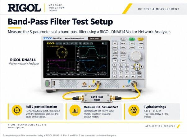
With a two-port Vector Network Analyzer (VNA), we can characterize both the transmission and reflection behavior of the filter in a single measurement. S21 shows how efficiently the signal passes through the device, while S11 and S22 reveal how well the input and output ports are matched. From the measured response, we can also determine the 3 dB bandwidth, center frequency and loaded Q, providing a clear picture of the filter’s overall performance and selectivity.
Setting Up the Measurement
For a band-pass filter, the DUT is connected between Port 1 and Port 2 of the VNA. Before starting the measurement, a full two-port calibration such as SOLT, ECal or TRL should be performed. Placing the calibration reference plane at the ends of the test cables, as close to the DUT as practical, helps minimize the influence of the measurement setup.
In this example, a filter centered around 4.26 GHz is measured using a RIGOL DNA Series VNA. The measurement covers 1–9 GHz with 1001 sweep points, a 10 kHz IF bandwidth and −5 dBm source power. S11, S21 and S22 are displayed together to evaluate transmission and matching behavior across the frequency range.
From the S21 Trace to the Key Filter Parameters
Once the measurement is configured, the S21 response provides the main view of the filter passband. The transmission level indicates insertion loss, while the frequencies at which the response crosses the −3 dB threshold define the lower and upper cutoff points.
On the RIGOL DNA Series, Bandwidth Search can automatically identify these points and calculate the corresponding center frequency, 3 dB bandwidth, insertion loss and loaded Q. This avoids repetitive manual marker positioning and makes it easier to obtain consistent results directly from the measured trace.
The loaded Q is calculated from the relationship:
Loaded Q = Center Frequency / 3 dB Bandwidth
A narrower bandwidth at the same center frequency corresponds to a higher loaded Q and therefore a more selective filter response.
Understanding the Result
In this example, the filter has a measured center frequency of 4.26930 GHz and a 3 dB bandwidth of 676.770 MHz, defined by the lower and upper cutoff frequencies of 3.93091 GHz and 4.60768 GHz. The measured insertion loss is −4.217 dB, while the calculated loaded Q is 6.308.
These values describe different aspects of the same filter response. S21 shows how the signal is transmitted through the filter and defines its passband, while S11 and S22 indicate how much signal is reflected at the input and output ports. Together, these measurements provide a more complete picture of filter performance than transmission alone.
Getting Repeatable Measurements
Reliable filter characterization also depends on the measurement setup. Calibration should be performed as close to the DUT plane as possible, and cable routing should remain stable after calibration. For narrowband or high-Q filters, sufficient sweep points are important to accurately resolve the response.
A narrower IF bandwidth can improve dynamic range and help when measuring deep stopbands or low-level signals, although this increases sweep time. Clean RF connections and consistent connector torque also help improve measurement repeatability. If additional noise reduction is required, averaging can be applied after selecting an appropriate IF bandwidth.
Explore the Measurement in More Detail
Want to go deeper into the measurement setup, calibration and filter characterization?
Read the full Application Note → rigol_blog_filter_article
Explore the RIGOL DNA Series → RIGOL Vector Network Analyzer DNA814
RIGOL Technologies EU GmbH
Friedrichshafener Str. 5
82205 Gilching
Telefon: +49 (89) 89418950
https://www.rigol.eu
European Marketing Specialist
E-Mail: dilara.kurtulmus@rigol.com


Das könnte dich ebenfalls interessieren
SPE – seamless and sustainable end-to-end connectivity
Zwei in Eins: OCT-Lösungen für Servo- und Motorleitungen